UML statechart diagrams are a powerful tool for modeling the behavior of complex systems. They provide a visual representation of the different states that an object can be in, and the transitions between those states. This allows developers to design and analyze the behavior of their systems in a clear and concise way. Here are some key things to know about UML statechart diagrams:
1. Introduction to Statechart Diagrams
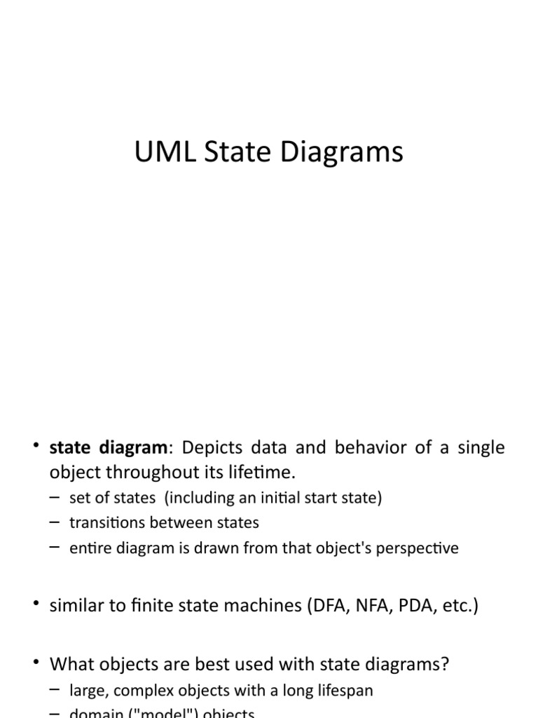
A statechart diagram is a type of diagram that shows the different states that an object can be in, and the events that cause the object to change from one state to another. It is a powerful tool for modeling the behavior of complex systems, and is commonly used in software development, embedded systems, and other fields.
2. Basic Elements of a Statechart Diagram
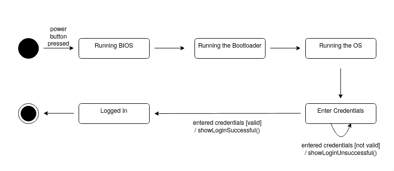
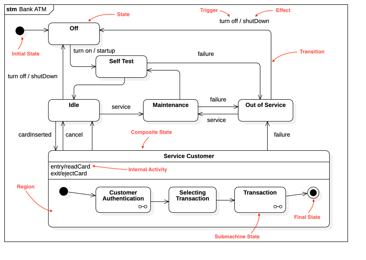
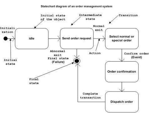
A statechart diagram consists of a number of basic elements, including states, transitions, and events. States are represented by rectangles, and transitions are represented by arrows between the states. Events are the triggers that cause the object to change from one state to another, and are often labeled on the transitions.
3. Types of States
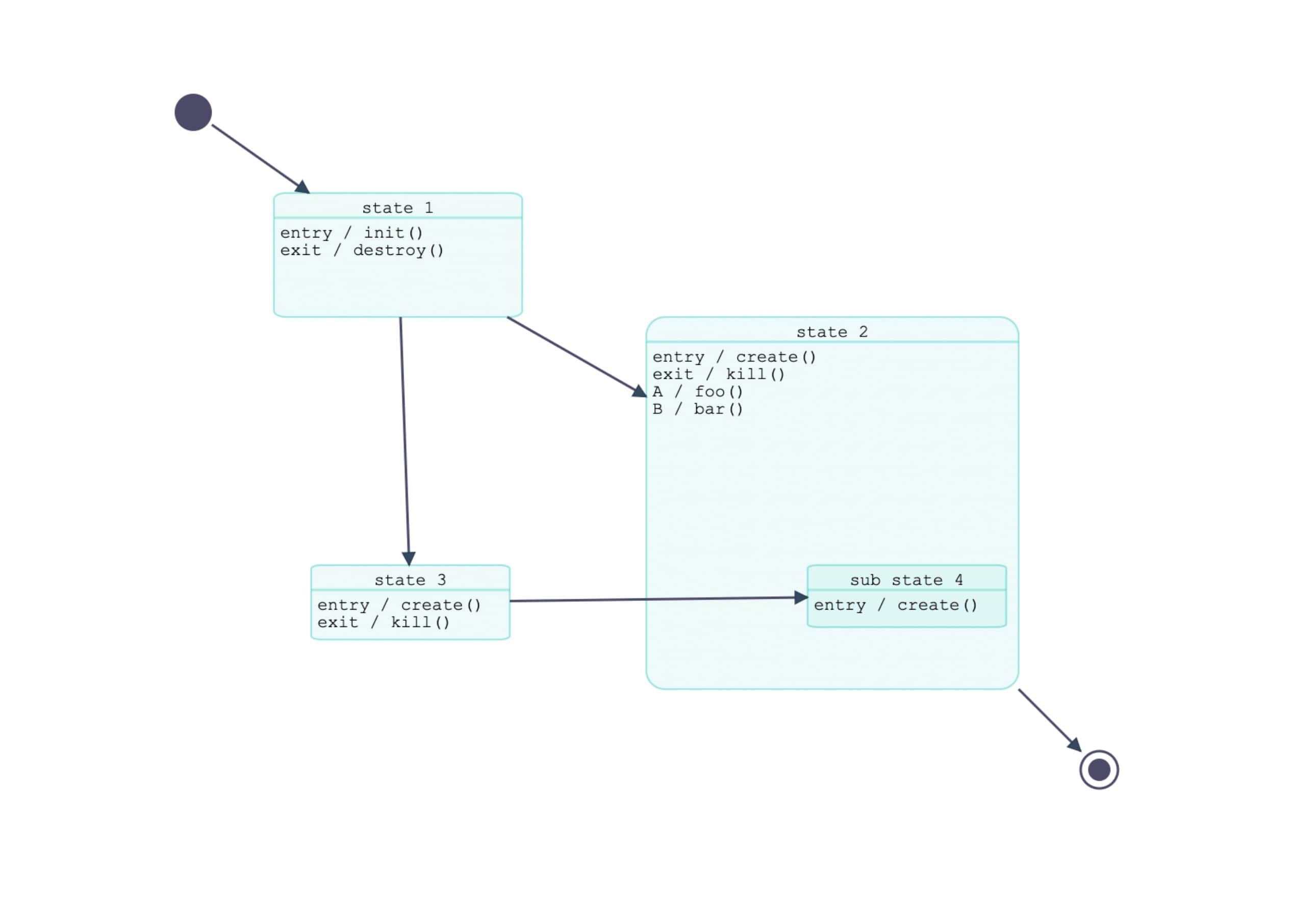
There are several types of states that can be represented in a statechart diagram, including simple states, composite states, and submachine states. Simple states are the basic building blocks of a statechart diagram, and represent a single state that an object can be in. Composite states, on the other hand, are used to represent a state that has multiple sub-states.
4. Transitions and Events
Transitions are the arrows that connect the states in a statechart diagram, and represent the changes from one state to another. Events are the triggers that cause these transitions to occur, and can be things like user input, network messages, or timer events. Transitions can also have guards, which are conditions that must be met in order for the transition to occur.
5. Statechart Diagrams and Object-Oriented Programming
Statechart diagrams are closely tied to object-oriented programming (OOP), and are often used to model the behavior of objects in an OOP system. Each state in a statechart diagram can be thought of as a method or procedure that the object can perform, and the transitions between states represent the changes in the object's state over time.
6. Modeling Complex Behavior with Statechart Diagrams
One of the key benefits of statechart diagrams is their ability to model complex behavior in a clear and concise way. By breaking down a complex system into its individual states and transitions, developers can gain a deeper understanding of how the system works, and can identify potential problems or areas for improvement.
7. Tools for Creating Statechart Diagrams
There are many tools available for creating statechart diagrams, ranging from simple drawing programs to complex modeling tools. Some popular tools include IBM Rational Rose, Microsoft Visio, and Graphviz. These tools can help developers create statechart diagrams quickly and easily, and can also provide features like simulation and validation.
8. Best Practices for Creating Statechart Diagrams
When creating a statechart diagram, there are several best practices to keep in mind. These include keeping the diagram simple and easy to understand, using clear and concise labels, and avoiding unnecessary complexity. It's also a good idea to use a consistent notation throughout the diagram, and to use colors or other visual effects to highlight important features.
9. Common Applications of Statechart Diagrams
Statechart diagrams have a wide range of applications, from software development to embedded systems and control systems. They are commonly used in fields like robotics, automotive systems, and medical devices, where complex behavior needs to be modeled and analyzed. They are also used in business process modeling, where they can help to identify and improve business processes.
10. Conclusion
In conclusion, UML statechart diagrams are a powerful tool for modeling the behavior of complex systems. They provide a visual representation of the different states that an object can be in, and the transitions between those states. By following best practices and using the right tools, developers can create statechart diagrams that are clear, concise, and effective, and that help to improve the design and analysis of complex systems.
If you are looking for UML State Diagrams Explained | Baeldung on Computer Science you've visit to the right web. We have 10 Images about UML State Diagrams Explained | Baeldung on Computer Science like UML State Diagrams | PDF, State Chart Diagram in UML | PDF | Unified Modeling Language | Computing and also UML Statechart Diagram – Demo applications & examples. Read more:
UML State Diagrams Explained | Baeldung On Computer Science
 www.baeldung.com
UML State Diagrams Explained | Baeldung on Computer Science
Understanding State Diagrams: A Tutorial - Go UML
 www.go-uml.com
Understanding State Diagrams: A Tutorial - Go UML
UML Statechart Diagram – Demo Applications & Examples
 www.jointjs.com
UML Statechart Diagram – Demo applications & examples
UML State Diagrams | PDF
 www.scribd.com
UML State Diagrams | PDF
Statechart Diagram | StarUML Documentation
 docs.staruml.io
Statechart Diagram | StarUML documentation
UML Statechart Diagrams - Startertutorials
 www.startertutorials.com
UML Statechart Diagrams - Startertutorials
Knowledge | Our Knowledge Base :)
 teamfcm.github.io
Knowledge | Our knowledge base :)
State Chart Diagram In UML | PDF | Unified Modeling Language | Computing
 www.scribd.com
State Chart Diagram in UML | PDF | Unified Modeling Language | Computing
UML State Diagrams With Draw.io - Draw.io
 drawio-app.com
UML state diagrams with draw.io - draw.io
Uml Statechart Diagrams Edraw Org Chart
 utpaqp.edu.pe
Uml Statechart Diagrams Edraw Org Chart
state chart diagram in uml. uml state diagrams explained. Uml state diagrams explained

