Logic flow charts are a crucial tool in various fields, including business, computer science, and engineering, as they provide a visual representation of the decision-making process. By using a flow chart, individuals can break down complex processes into simpler, more manageable steps, and identify potential problems or areas for improvement. In this article, we will explore the key components and benefits of logic flow charts.
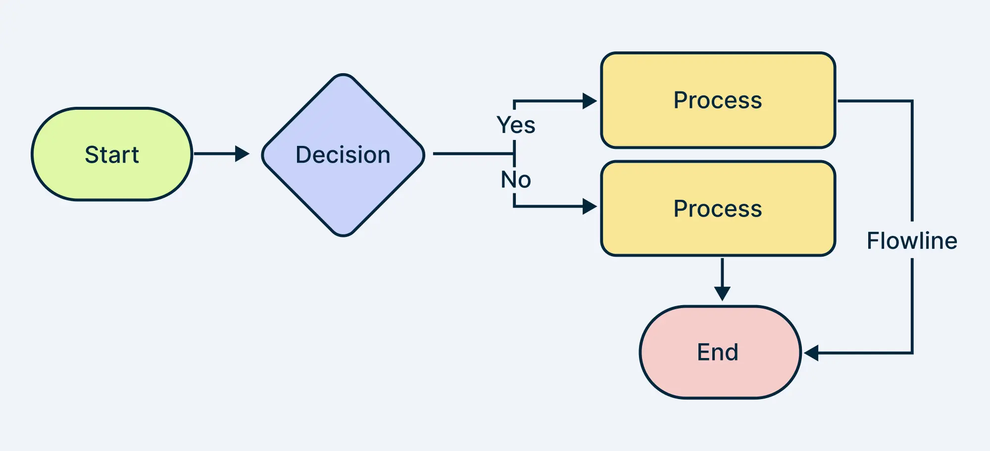
1. Start and End Points
A logic flow chart typically begins with a start point, which represents the beginning of the process, and ends with an end point, which signifies the conclusion of the process. These points are usually denoted by oval or rounded rectangle shapes, and are connected by arrows to indicate the flow of the process. The start and end points provide a clear understanding of the process boundaries and help to define the scope of the flow chart.
2. Decision Diamonds
Decision diamonds are used to represent decision-making points in the process, where a choice or a condition is evaluated. These diamonds are typically marked with a question or a condition, and have multiple arrows emerging from them, each representing a possible outcome or path. Decision diamonds allow users to visualize the different scenarios and outcomes, and to identify the potential consequences of each decision.
3. Action Boxes
Action boxes, also known as process boxes, represent the tasks or actions that need to be performed during the process. These boxes are usually rectangular in shape and contain a brief description of the task or action. Action boxes help to break down the process into smaller, more manageable steps, and provide a clear understanding of what needs to be done at each stage.
4. Conditional Arrows
Conditional arrows are used to connect the decision diamonds to the action boxes or other decision diamonds, and represent the flow of the process based on the conditions or decisions made. These arrows are usually labeled with a condition or a question, and help to define the logic of the process. Conditional arrows enable users to visualize the different paths that the process can take, and to identify the potential bottlenecks or areas for improvement.
5. Loops and Iterations
Loops and iterations are used to represent repetitive tasks or actions that need to be performed during the process. These loops can be represented by a circular arrow or a feedback loop, and help to simplify the flow chart by avoiding repetition. Loops and iterations enable users to model complex processes that involve repetitive tasks, and to identify areas where automation or optimization can be applied.
6. Subroutines and Modules
Subroutines and modules are used to represent self-contained tasks or processes that can be reused in different parts of the flow chart. These subroutines and modules help to simplify the flow chart by breaking down complex processes into smaller, more manageable components. Subroutines and modules also enable users to reuse and share knowledge, and to reduce the complexity of the flow chart.
7. Error Handling and Exceptions
Error handling and exceptions are used to represent scenarios where an error or an unexpected event occurs during the process. These exceptions can be represented by a separate path or a parallel flow chart, and help to define the actions that need to be taken in case of an error or exception. Error handling and exceptions enable users to anticipate and mitigate potential risks, and to ensure that the process is robust and reliable.
8. swimlane Diagrams
Swimlane diagrams are used to represent the roles and responsibilities of different stakeholders or teams involved in the process. These diagrams help to clarify the communication and collaboration requirements between different stakeholders, and enable users to identify potential bottlenecks or areas for improvement. Swimlane diagrams are particularly useful in business process modeling, where multiple stakeholders and teams are involved.
9. Flow Chart Symbols and Notations
Flow chart symbols and notations are used to represent the different components and elements of the process, such as decision diamonds, action boxes, and conditional arrows. These symbols and notations help to standardize the flow chart and ensure that it is easily understandable by all stakeholders. Flow chart symbols and notations also enable users to communicate complex ideas and processes in a simple and concise manner.
10. Best Practices and Common Mistakes
Best practices and common mistakes are essential considerations when creating a logic flow chart. Best practices include keeping the flow chart simple and concise, using standard symbols and notations, and testing the flow chart for errors and exceptions. Common mistakes include using ambiguous or unclear language, failing to define the process boundaries, and neglecting to test the flow chart. By following best practices and avoiding common mistakes, users can create effective and efficient logic flow charts that meet their needs and requirements.
If you are looking for What is a Logic Chart, and How does it Help you Make Decisions? you've visit to the right place. We have 10 Images about What is a Logic Chart, and How does it Help you Make Decisions? like (PDF) APPLIED-LOGIC FLOW CHART | John Corcoran - Academia.edu, Flow Chart For General Logic - Computers Hub! and also (PDF) APPLIED-LOGIC FLOW CHART | John Corcoran - Academia.edu. Here it is:
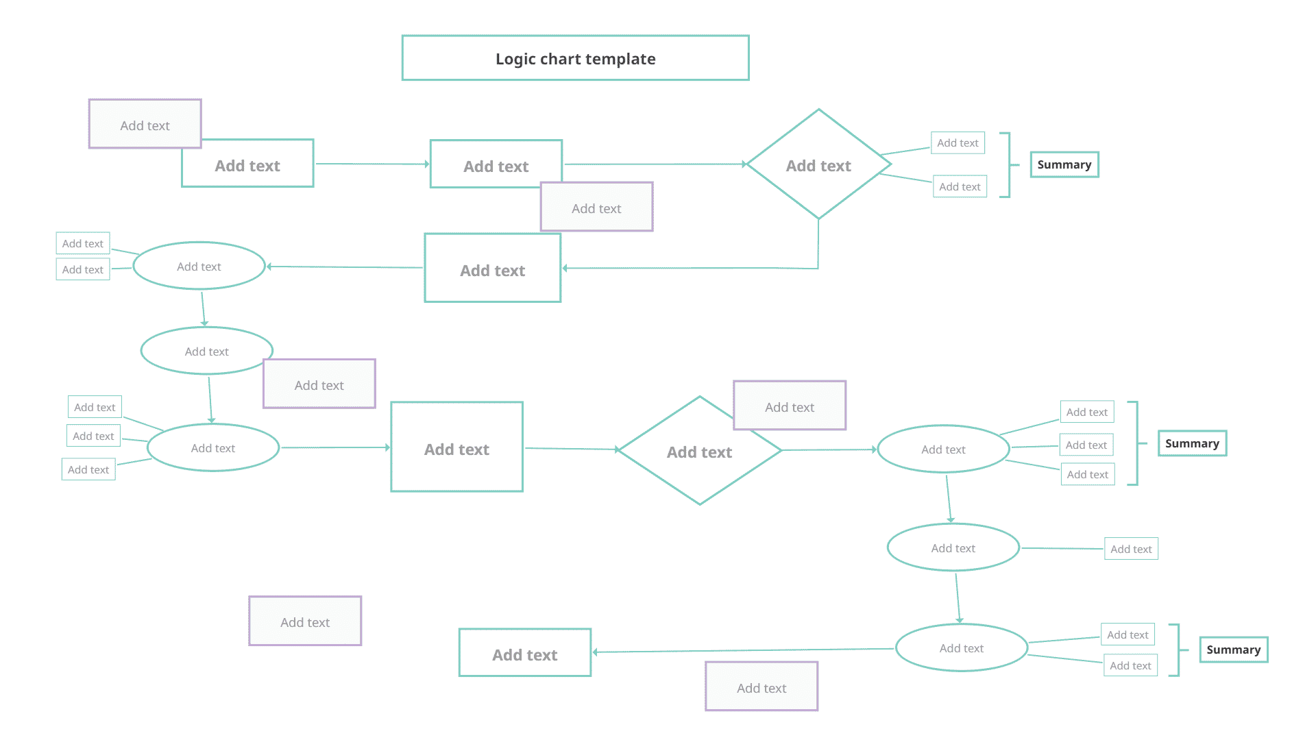
What Is A Logic Chart, And How Does It Help You Make Decisions?
 www.mindomo.com
What is a Logic Chart, and How does it Help you Make Decisions?
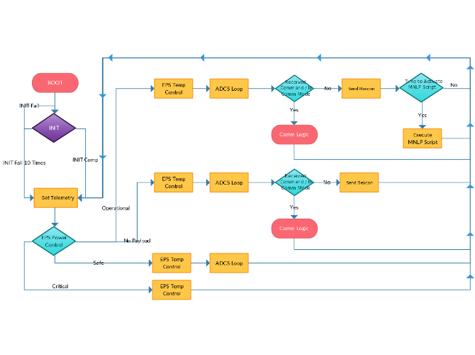
Logic Flow Chart Of The System | Download Scientific Diagram
 www.researchgate.net
Logic Flow Chart of the System | Download Scientific Diagram
Flow Chart Of Decision Logic | Download Scientific Diagram
 www.researchgate.net
Flow Chart of Decision Logic | Download Scientific Diagram
Flow Chart For General Logic - Computers Hub!
 www.computershub.org
Flow Chart For General Logic - Computers Hub!
Flow Chart Logo
 fity.club
Flow Chart Logo
A Flow Chart For A Fuzzy Logic Controller | Download Scientific Diagram
 www.researchgate.net
A flow chart for a fuzzy logic controller | Download Scientific Diagram
Algorithm, Chart, Flow, Logic, Plan, Process Icon
Algorithm, chart, flow, logic, plan, process icon
A Chart Showing The Flow Of Logic. | Download Scientific Diagram
 www.researchgate.net
A chart showing the flow of logic. | Download Scientific Diagram
Algorithm, Chart, Flow, Flowchart, Logic, Process, System Icon
Algorithm, chart, flow, flowchart, logic, process, system icon ...
(PDF) APPLIED-LOGIC FLOW CHART | John Corcoran - Academia.edu
 www.academia.edu
(PDF) APPLIED-LOGIC FLOW CHART | John Corcoran - Academia.edu
flow chart for general logic. A chart showing the flow of logic.. Logic flow chart of the system

